Background
Regardless of the platform – tripod laser scanning, mobile LiDAR, airborne LiDAR, or UAV image-based systems – the optimized organization and accessibility of project data contributes directly to its value. The ability to share and locate data efficiently and inexpensively facilitates quickly feeding downstream operations with high value models, asset, and analysis information. This information has been demonstrated to yield extremely high value returns in support of typical civil infrastructure projects.
Objective
It is the objective of Technote #1034 to provide requirements for project data organization designed to optimize cloud storage and overall TopoDOT® process performance. These requirements are to be employed by a company, agency or internal department requesting point cloud project data in support of a civil infrastructure project. Properly prepared and organized, the delivered project data can be seamlessly uploaded to the selected storage medium. Project data and supporting metadata is then easily located and accessed in minutes from a standard workstation without any high performance or expensive IT infrastructure.
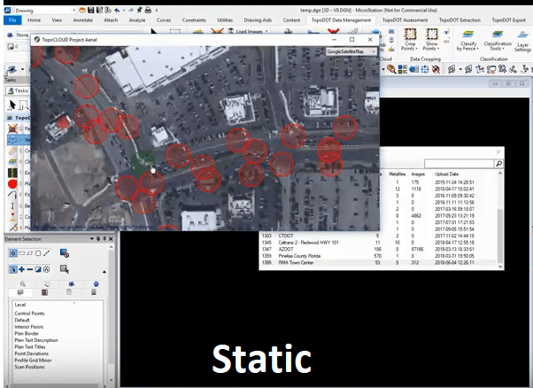
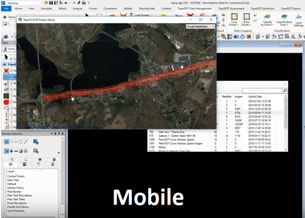
As an example, please select the following videos to demonstrate how efficiently project data can be identified, located and accessed when the processes summarized in TechNote #1034 are successfully executed.
This current version of Technote #1034 features requirements for two categories of point cloud generating systems, static and mobile laser scanning. Within each section, suggested text articulating data organization requirements are provided. Following the requirements section, a link to a detailed process complete with videos will demonstrate an efficient workflow for implementing these data organization requirements.
Data Organization Requirements for Static Laser Scanning Systems
Static laser scanning systems acquire data from a stable non-moving platform such as a tripod. Multiple individual scans are aligned to each other and within the project coordinate system using external reference targets at known locations and/or integrated GPS positioning methods. The data organization process presented here is designed to maintain the lineage of each individual Static laser scanning systems acquire data from a stable non-moving platform such as a tripod. Multiple individual scans are aligned to each other and within the project coordinate system using external reference targets at known locations and/or integrated GPS positioning methods. The data organization process presented here is designed to maintain the lineage of each individual scan position to its’ associated data, alignment statistics and reference control coordinates. scan position to its’ associated data, alignment statistics and the original control.
Directory Tree Structure
Requirement: Project data shall be delivered in the following directory tree structure. Note that bold labels are directory folder names. All files generated with TopoDOT® should be placed directly within this local tree structure. File references for downstream TopoShare™ upload operations are relative. Thus the entire tree structure should be exported without changing any “relative” file locations. Detailed requirements corresponding to the data contained in each directory are provided below.
Project ID# Name
- E57 Project Data
- Name E57-1 Data File
- Name E57-2 Data File
- Name E57-n Data File
- TopoDOT Optimized Data
- Name E57-1
- DOT Files
- .dot Files
- .tvw File
- Image Project
- .jpg Files
- .iprj File
- .lst File
- .cal Files
- DPEG
- .dpeg Files
- .dprj Files
- DOT Files
- Name E57-2
- DOT Files
- .dot Files
- .tvw File
- Image Project
- .jpg Files
- .iprj File
- .lst File
- .cal Files
- DPEG
- .dpeg Files
- .dprj Files
- DOT Files
- Name E57-n
- DOT Files
- .dot Files
- .tvw File
- Image Project
- .jpg Files
- .iprj File
- .lst File
- .cal Files
- DPEG
- .dpeg Files
- .dprj Files
- DOT Files
- Name E57-1
- Metadata
- Control
- .csv, .doc, .pdf
- Quality Assessments
- .rda (TopoDOT generated quality summaries), .png with .pngw (world file)
- Line work
- .json
- General Overviews
- .png with .pngw (world file)
- CAD & GIS
- .dgn, .dwg, dxf, . . .
- Project Information
- .doc, .pdf, . . . (contracts, RFP, proposal, etc.)
- Control
E57 Project Data
Requirement: Data acquired by the laser scanning system will be exported in the ASTM E57 open format. If calibrated images were acquired, they will also be exported in the E57 format. It will be considered good practice to deliver each day’s acquisition as an individual E57 project, i.e. “Name E57-n”. However this is “required” when a system camera (typically external) must be recalibrated after dismount/mount. In this case, a new Name E57-n file is necessary for each new camera calibration. This file(s) will reside in the Project ID# Name\E57 Project Data directory.
The E57 format is an open format supported by every primary supplier of laser scanning equipment. E57 assures that the location of each scan position is exported and tagged to the corresponding points generated at the corresponding scan position. All calibration information is also maintained within the project file. Maintaining the provenance of each individual scan position along with calibration metadata is critical to downstream project quality assessment and efficient access from the cloud storage medium.
DOT Files
Requirement: The Name E57-n format data project(s) point cloud files will be intelligently decimated and reformatted to the TopoDOT native DOT format. The process will generate .dot files corresponding to each individual scan location, along with a single .tvw mapping file, and an image project. All files will be stored in the Project ID# Name\TopoDOT Optimized Data\Name E57-n directory(s).
E57 format point cloud files contain all original data. This process calls for reformatting the E57 format to the native TopoDOT® .dot format. Then the files will be intelligently decimated by about 60% as they are each loaded into TopoDOT without any loss of information. Quality assessments can be made at this time. Then these .dot files will be exported to overwrite the original larger .dot files. These optimized .dot files will load faster, require less memory and generally enhance TopoDOT® extraction performance. Details of this process are documented online via the link at the end of this section.
Image Project
Requirement: The Name E57-n calibrated image file will be reformatted to the TopoDOT® Open Calibrated Image file format. Resulting .jpg format images and individual .iprj (project info), .lst (image position, orientation and relative path) and .cal (camera calibration file) will be stored in Project ID# Name\TOPODOT Optimized Data\Name E57-n\Image Project directory.
The TopoDOT® image file format facilitates quick location and access of any calibrated image. Since camera calibration parameters may change as cameras are dismounted and mounted over several acquisition days, the TopoDOT® camera file format accommodates multiple camera calibrations within the same project. For further information, reference Technote #1009 TopoDOT® Open Calibrated Image File Format.
Control
Requirement: Any reference control network coordinates shall be included in standard .csv file format within the Project ID# Name\Metadata\Control directory. Also included should be any documents relevant to the origin and documentation of the control.
In addition to facilitating project cloud storage and sharing, Technote #1034 is designed to store project metadata relevant to data quality. Thus all information establishing lineage of point cloud and image data to control is kept within the project directory. This data is subsequently used in evaluating and summarizing project data quality.
Quality Assessments
Requirement: Project quality evaluation and summary data generated in TopoDOT® in the form of .rda and .png with .pngw files will be stored in Project ID# Name\Metadata\Quality Assessments directory.
TopoDOT® offers several tools for evaluating project data quality. For detailed description of these procedures and tools see Technote #1021: Establishing Requirements, Extracting Metrics and Evaluating Quality of LiDAR Data. Note also that these procedures will be summarized in another link to a supplemental document providing the workflow associated with this Technote #1034. The files generated here document relative scan to scan alignment as well as data alignment to control reference coordinates across the project. TopoDOT® extracts the new .rda file from these results to very concisely summarize overall data quality. See the link to Technote #1034 procedures for more detail.
General Overviews
Requirement: Project overview images (non-assessment) generated in TopoDOT® in the form of .png with .pngw files will be stored in Project ID# Name\Metadata\General Overviews directory.
TopoDOT has tools to generate overview raster images of various display modes for visualizing the point cloud using lightweight image files.
CAD, GIS, & Analysis
Requirement: Products and/or analyses extracted from project should remain with the project and stored in the Project ID# Name\Metadata\CAD & GIS directory. These files typical include but are not restricted to .dgn, dwg, .shp, .xls and similar formats.
Any models, assets, features, or analyses extracted from the project data should be continuously appended to the project thereby making it accessible to others and avoiding repetition of effort.
Project Information
Requirement: General project information such as RFP, proposals, contracts, etc. should be appended to project data in the Project ID# Name\Metadata\Project Information directory.
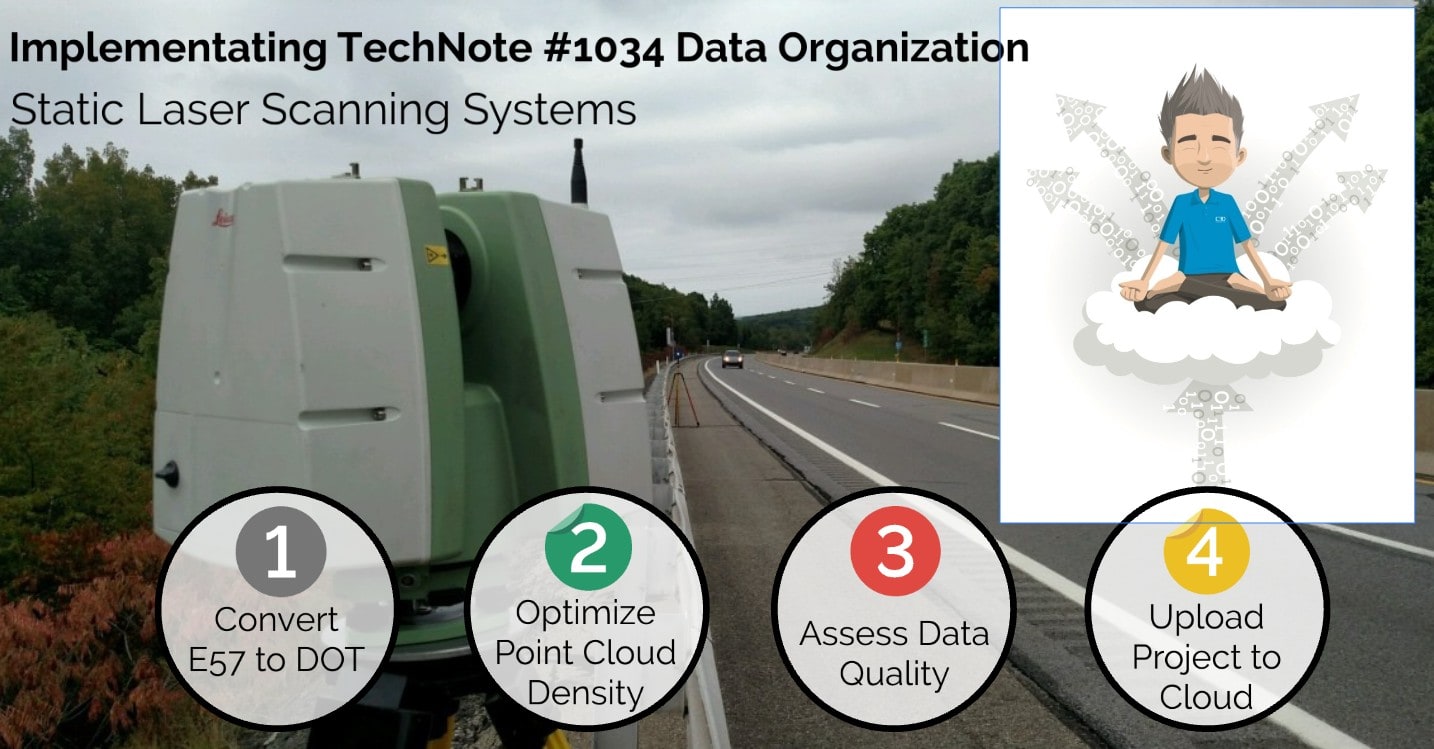
Implementing TechNote #1034 Data Organization Requirements
Implementation of aforementioned requirements can be executed in a three step process as shown below. Once these files have been created and organized in this directory tree structure, TopoShare™ can be employed by the administrator to upload the project to the selected storage medium, typically FTP or Amazon S3. Click on the following image to link to the Prezi formatted presentation complete with videos to see this process executed.
Data Organization Requirements for Mobile Laser Scanning Systems
Mobile laser scanning systems acquire data from a moving platform. Point cloud data is referenced to a vehicle path trajectory acquired from GPS/IMU data. Data accuracy is increased by realigning trajectory relative to higher accuracy reference coordinates. The data organization process presented here is designed to maintain a lineage from data associated with individual trajectories, their relative alignment and, if available, to the original reference control coordinates.
Directory Tree Structure
Requirement: Project data shall be delivered in the following data tree structure. Note that bold labels are directory names. All files generated with TopoDOT® should be placed directly within this local tree structure. File references for downstream TopoShare™ upload operations are relative. Thus the entire tree structure should be exported without changing any “relative” file locations. Detailed requirements corresponding to the data contained in each directory are provided below.
Project ID# Name
- Raw Project Data
- LAS Files
- .las Files
- Image Files
- Image Project 1
- .iprj File
- .lst File
- Subfolders as delivered
- .jpg Files
- .cal Files
- Image Project 2
- .iprj File
- .lst File
- Subfolders as delivered
- .jpg Files
- .cal Files
- Image Project 1
- LAS Files
- TopoDOT Optimized Data
- DOT Files
- .dot Files
- .tvw File
- DPEG
- .dpeg Files
- .dprj Files
- DOT Files
- Metadata
- Control
- .csv, .doc, .pdf
- Quality Assessments
- .rda (TopoDOT generated quality summaries), .png with .pngw (world file)
- Line Work
- .json
- General Overviews
- .png with .pngw (world file)
- CAD & GIS
- .dgn, .dwg, dxf, . . .
- Project Information
- .doc, .pdf, . . . (contracts, RFP, proposal, etc.)
- Control
LAS Files
Requirement: Data should be delivered in the .las file format with several constraints placed on each file. Extremely large file sizes should be avoided, thus data acquired during any “single trajectory” along the corridor should not exceed more than a 2-3 miles in length without starting another file. No single file should contain “overlapping” data generated from more than one vehicle trajectory along a corridor “unless” the data associated with each trajectory can be identified using the Point Source ID tag in the .las format. Otherwise each acquisition trajectory must save data in separate .las files. These files should be placed in the Project ID# Name\Raw Project Data\LAS Files directory.
Of primary importance in the delivery of these original .las files is that no single file contain overlapping data from multiple vehicle trajectories. If this were the case, there is no means to uniquely identify the data from each pass therefore making it impossible to execute many automated quality analyses in TopoDOT. Furthermore there would be no way to actively manage the data by turning different passes on and off during the extraction processes. Misalignments and such would thus be “baked” into the combined point cloud.
Image Files
Requirement: Ideally, a single image project should contain data from all cameras. Alternatively, a separate image project associated with each individual trajectory file is acceptable but not preferred. Images should be exported in the TopoDOT® image format. Images exported in the TopoDOT® format will provide .jpg, .iprj, .lst and .cal files. They will be placed in the Project ID# Name\Raw Project Data\Image Files\Image Project n directory.
As every major mobile laser scanning system provides a TopoDOT® format image export option, this should be a requirement. Manufacturers don’t implement the TopoDOT® export in exactly the same way, so two alternative structures are offered. Images exported using the TopoDOT® format are configured for upload to the storage medium and downstream access. Thus no further processing is required. For further information, reference Technote #1009 TopoDOT® Open Calibrated Image File Format.
DOT Files
Requirement: Define a tile configuration along the corridor. Parse delivered .las point cloud files into individual separate .dot files with data confined to its’ respective tile. Generate a .tvw mapping file comprised of spatial coordinates within each tile with the relative path to the corresponding .dot data file. Tiles along a corridor should extend in width (orthogonal to vehicle trajectory) to the practical limits of the corridor project. The length of each tile should not exceed about 500 feet (130m). The amount of data within any one tile should be well less than about 30 million points. These files should be placed in the Project ID# Name\TopoDOT Optimized Data\DOT Files directory.
Generating these files is a highly automated TopoDOT® process. Note that these original .las files might be very large. Thus it is typical to employ TopoDOT® import decimation option to load files as a spatial reference, say every 10th point or more. Then simply establish a polyline along the corridor, select it, and generate specified tiles automatically. After the tiles are generated, they can be modified using standard CAD functions in the TopoDOT® environment.
Note that individual modifications may be necessary at intersections where tiles will overlap. If this is not done, only the first tile created in overlapping area will contain the corresponding data thereby leaving a data “hole” in the underlying tile. Terminate each tile at the boundary of the other prior to parsing the .las data to avoid this.

Control
Requirement: Any reference control network coordinates shall be included in standard .csv file format within the Project ID# Name\Metadata\Control directory. Also included should be any documents relevant to the origin and documentation of the control.
In addition to facilitating project cloud storage and sharing, Technote #1034 is designed to store project metadata relevant to data quality. Thus all information establishing lineage of point cloud and image data to control is kept within the project directory. This data is subsequently used in evaluating and summarizing project data quality.
Quality Assessment
Requirement: Project quality evaluation and summary data generated in TopoDOT® in the form of .rda and .png with .pngw files will be stored in Project ID# Name\Metadata\Quality Assessments directory.
TopoDOT® offers several tools for evaluating project data quality. For detailed description of these procedures and tools see Technote #1021: Establishing Requirements, Extracting Metrics and Evaluating Quality of LiDAR Data. Note also that these procedures will be summarized in another link to a supplemental document providing the workflow associated with this Technote #1034. The files generated here document relative overlapping scan to scan alignment as well as data alignment to control reference coordinates across the project. TopoDOT® extracts the new .rda file from these results to very concisely summarize overall data quality. See the link to Technote #1034 procedures for more detail.
General Overviews
Requirement: Project overview images (non-assessment) generated in TopoDOT® in the form of .png with .pngw files will be stored in Project ID# Name\Metadata\General Overviews directory.
TopoDOT has tools to generate overview raster images of various display modes for visualizing the point cloud using lightweight image files.
CAD, GIS, & Analysis
Requirement: Products and/or analyses extracted from project should remain with the project and stored in the Project ID# Name\Metadata\CAD & GIS directory. These files typical include but are not restricted to .dgn, dwg, .shp, .xls and similar formats.
Any models, assets, features, or analyses extracted from the project data should be continuously appended to the project thereby making it accessible to others and avoiding repetition of effort.
Project Information
Requirement: General project information such as RFP, proposals, contracts, etc. should be appended to project data in the Project ID# Name\Metadata\Project Information directory.
Implementing Technote #1034 Data Organization Requirements
Implementation of aforementioned requirements can be executed in a two step process as shown below. Once these files have been created and organized in this directory tree structure, TopoShare™ can be employed by the administrator to upload the project to the selected storage medium, typically FTP or Amazon S3. Click on the following image to link to the Prezi formatted presentation complete with videos to see this process executed.

0 Comments